- 您现在的位置:买卖IC网 > Sheet目录871 > OKL-T/3-W12P-C (Murata Power Solutions Inc)CONV DC/DC 15W 12VIN 3AOUT SMD
�� �
�
�OKL-T/3-W12� Series�
�Programmable� Output� 3-Amp� i� LGA� SMT� PoLs�
�TO�
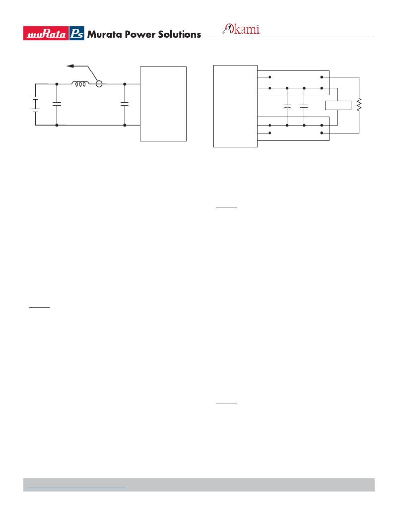
�OSCILLOSCOPE�
�CURRENT�
�PROBE�
�+�
�L� BUS�
�+VIN�
�+VOUT�
�V� IN�
�–�
�+�
�C� BUS�
�C� IN�
�C1�
�C2�
�SCOPE�
�R� LOAD�
�–�
�-VIN�
�C� IN� =� 2� x� 100μF,� ESR� <� 700mΩ� @� 100kHz�
�C� BUS� =� 1000μF,� ESR� <� 100mΩ� @� 100kHz�
�L� BUS� =� 1μH�
�Figure� 4.� Measuring� Input� Ripple� Current�
�Minimum� Output� Loading� Requirements�
�All models regulate within speci?cation and are stable under no load to full�
�load� conditions.� Operation� under� no� load� might� however� slightly� increase�
�output� ripple� and� noise.�
�Thermal� Shutdown�
�To� prevent� many� over� temperature� problems� and� damage,� these� converters�
�include� thermal� shutdown� circuitry.� If� environmental� conditions� cause� the�
�temperature� of� the� DC/DC’s� to� rise� above� the� Operating� Temperature� Range�
�up� to� the� shutdown� temperature,� an� on-board� electronic� temperature�
�sensor� will� power� down� the� unit.� When� the� temperature� decreases� below�
�the� turn-on� threshold,� the� converter� will� automatically� restart.� There� is� a�
�small� amount� of� hysteresis� to� prevent� rapid� on/off� cycling.�
�CAUTION� :� If� you� operate� too� close� to� the� thermal� limits,� the� converter�
�may� shut� down� suddenly� without� warning.� Be� sure� to� thoroughly� test� your�
�application� to� avoid� unplanned� thermal� shutdown.�
�Temperature� Derating� Curves�
�The� graphs� in� this� data� sheet� illustrate� typical� operation� under� a� variety� of�
�conditions.� The� Derating� curves� show� the� maximum� continuous� ambient� air�
�temperature� and� decreasing� maximum� output� current� which� is� accept-�
�able� under� increasing� forced� air?ow� measured� in� Linear� Feet� per� Minute�
�(“LFM”).� Note� that� these� are� AVERAGE� measurements.� The� converter� will�
�accept� brief� increases� in� current� or� reduced� air?ow� as� long� as� the� average�
�is� not� exceeded.�
�Note� that� the� temperatures� are� of� the� ambient� air?ow,� not� the� converter�
�itself� which� is� obviously� running� at� higher� temperature� than� the� outside�
�air.� Also� note� that� very� low� ?ow� rates� (below� about� 25� LFM)� are� similar� to�
�“natural� convection”,� that� is,� not� using� fan-forced� air?ow.�
�Murata� Power� Solutions� makes� Characterization� measurements� in� a�
�closed� cycle� wind� tunnel� with� calibrated� air?ow.� We� use� both� thermocou-�
�-VOUT�
�C1� =� 1μF�
�C2� =� 10μF�
�LOAD� 2-3� INCHES� (51-76mm)� FROM� MODULE�
�Figure� 5.� Measuring� Output� Ripple� and� Noise� (PARD)�
�CAUTION� :� These� graphs� are� all� collected� at� slightly� above� Sea� Level�
�altitude.� Be� sure� to� reduce� the� derating� for� higher� density� altitude.�
�Power� Good� Output�
�The� PGood� signal� is� an� open� drain� output� requiring� a� user’s� external� pullup�
�resistor� to� +5V� or� less� referred� to� -Vin.� PGood� indicates� when� the� converter�
�has� stabilized� and� the� output� is� approximately� within� regulation.� PGood� is�
�TRUE� (open� drain,� high� impedance� state)� if� the� converter’s� power� output�
�voltage� within� about� +/-10%� of� the� setpoint.� When� PGood� is� FALSE� (satu-�
�rated� low� impedance� state,� LOW),� the� output� resides� within� about� +0.4V� or�
�less� referred� to� -Vin,� depending� on� the� pullup� current.�
�Note� that� PGood� does� not� directly� measure� an� output� overcurrent� condi-�
�tion.� However,� gross� overcurrent� or� output� short� circuit� will� set� PGood� to�
�FALSE� (less� than� +0.4V� saturation,� low� impedance� condition).� Because� of�
�the� open� drain� design,� several� converters� may� connect� their� PGood’s� in�
�parallel� with� a� common� external� pullup� resistor� in� a� wired-OR� method.�
�The� following� conditions� will� render� PGood� as� FALSE� (Low):�
�+Vout� is� greater� than� 10%� error� from� Vset.�
�Softstart� is� active� and� not� yet� complete.�
�An� input� undervoltage� is� present� at� +Vin.�
�An� output� short� circuit� has� occurred.�
�An� over� temperature� (OT)� condition� has� occurred.�
�At� power� up,� before� the� converter� has� achieved� stable� regulation,� PGood�
�approximates� a� forward-biased� diode� to� ground.�
�CAUTION� -� PGood� is� connected� directly� to� the� PWM� controller� and� a�
�small� signal� FET� inside� the� PWM.� Use� electrostatic� protection.� The� PWM�
�may� be� destroyed� by� inadvertant� static� discharge� or� excess� current� into�
�the� PGood� signal.� Pull� down� current� should� be� limited� to� 5� mA� maximum�
�and� the� external� pullup� voltage� should� never� exceed� +5V� referred� to� the�
�negative� input,� -Vin.�
�ples� and� an� infrared� camera� system� to� observe� thermal� performance.�
�www.murata-ps.com/support�
�MDC_OKL-T/3-W12� Series.B01� Page� 14� of� 17�
�发布紧急采购,3分钟左右您将得到回复。
相关PDF资料
OKL-T/3-W5N-C
CONV DC/DC 9.9W 3A 5VIN SMD
OKL-T/6-W12N-C
CONV DC/DC 30W 6A 12VIN SMD
OKL-T/6-W5N-C
CONV DC/DC 19.8W 6A 5VIN SMD
OKR-T/10-W12-C
CONV DC/DC 10A 12VIN POL SIP
OKR-T/3-W12-C
CONV DC/DC 15W 12VIN SIP
OKR-T/6-W12-C
CONV DC/DC 6A 12VIN POL SIP
OKX-T/3-D12N-C
DC-DC CONVRT 0.7525-5.5V 3A 5SIP
OKX-T/3-W5P-C
DC-DC CONVRT 0.7525-3.6V 3A 5SIP
相关代理商/技术参数
OKL-T/3-W12P-C
制造商:Murata Power Solutions 功能描述:DC/DC Converter
OKL-T/3-W5
制造商:Murata Power Solutions 功能描述:- Rail/Tube
OKL-T/3-W5N-C
功能描述:DC/DC转换器 5Vin 0.6-3.63Vout 3A 9.9W Neg Polarity
RoHS:否 制造商:Murata 产品: 输出功率: 输入电压范围:3.6 V to 5.5 V 输入电压(标称): 输出端数量:1 输出电压(通道 1):3.3 V 输出电流(通道 1):600 mA 输出电压(通道 2): 输出电流(通道 2): 安装风格:SMD/SMT 封装 / 箱体尺寸:
OKL-T/3-W5P-C
功能描述:DC/DC转换器 5Vin 0.6-3.63Vout 3A 9.9W Pos Polarity
RoHS:否 制造商:Murata 产品: 输出功率: 输入电压范围:3.6 V to 5.5 V 输入电压(标称): 输出端数量:1 输出电压(通道 1):3.3 V 输出电流(通道 1):600 mA 输出电压(通道 2): 输出电流(通道 2): 安装风格:SMD/SMT 封装 / 箱体尺寸:
OKL-T/6-W12N-C
功能描述:DC/DC转换器 12Vin .59-5.5Vout 6A 30W Neg Polarity
RoHS:否 制造商:Murata 产品: 输出功率: 输入电压范围:3.6 V to 5.5 V 输入电压(标称): 输出端数量:1 输出电压(通道 1):3.3 V 输出电流(通道 1):600 mA 输出电压(通道 2): 输出电流(通道 2): 安装风格:SMD/SMT 封装 / 箱体尺寸:
OKL-T/6-W12N-C
制造商:Murata Power Solutions 功能描述:DC/DC Converter
OKL-T/6-W12P-C
功能描述:DC/DC转换器 12Vin .59-5.5Vout 6A 30W Pos Polarity
RoHS:否 制造商:Murata 产品: 输出功率: 输入电压范围:3.6 V to 5.5 V 输入电压(标称): 输出端数量:1 输出电压(通道 1):3.3 V 输出电流(通道 1):600 mA 输出电压(通道 2): 输出电流(通道 2): 安装风格:SMD/SMT 封装 / 箱体尺寸:
OKL-T/6-W5
制造商:MURATA 制造商全称:Murata Manufacturing Co., Ltd. 功能描述:Programmable Output 6-Amp iLGA SMT PoLs